Sunday, January 31, 2010
Track
I was reading the Salt Lake Route series in the Mar MR today. The discussion about the Kato Unitrak double track super-elevated curves really has my attention. Since a lot of use like modern equipment maybe we should consider that. Double stacks and high cars really look good on super-elevated curves. It is worth discussing.
Thursday, January 28, 2010
Wednesday, January 27, 2010
A Response to "Wiring"
Milt,
You have Hit the Nail on the Head with regard to the wiring issues we will face. I believe that we will see similar challenges in track and scenery design as well. Unless the tracks always hit exactly the same location at the end of each module (aka N-Trak) we cannot move modules around. The scenery really also needs to match ... imagine if a mountain continued from one section to another ... what happens when one module is missing?
In order to facilitate true automation, a permanent layout is really expected with components that are always in the same place. If we use a modular design, and expect the individual modules to come and go, as well as move around, we will have a very difficult time designing an automation system that will work from setup to setup. In fact, the whole concept of train detection and signaling requires a constant track plan.
At the next meeting we can review some of the wiring issues and look closely at the wiring designs I have done so far. Then we can discuss the positives & negatives of a modular vs. permanent layout.
Let's hear from everybody on this issue ... it really is one we need to deal with as a group!
Richard
Wiring
I am still struggling with the wiring concept for our proposed layout from a construction standpoint. Since we are likely to be modular for quite some time this has to be quick and easy to set up and tear down. I am shooting for way less time than N-Trak. I think the drawer idea is super, but what bothers me is we are likely not to have the same modules in the layout at all times. It seems this could confuse the system. And we don't want to be running a new set of wires back to the drawer each time we add a module. One solution might be to have each module as a detection zone, but this still requires a set of wires for each module and doesn't tell the computer which module it is. And how long should the wires be? I understand that every section does not have to be a detection zone so we could require certain modules to be in specific places every time we set-up. But this could severely limit flexibility. I wonder if it is possible to add a decoder to each module that could identify it to the computer, or could we use bluetooth to hook it up?
I think all the other problems of construction are fairly easy to solve. This one has me running in circles. We need everyones input on how this can be done. No idea is a bad one, but no ideas is bad. We need true plug and play for this.
Tuesday, January 26, 2010
Saturday, January 23, 2010
Thursday, January 21, 2010
Era
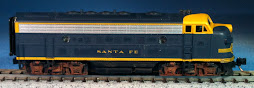
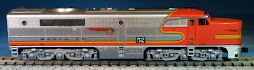
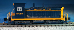
I like transition era because of steam. But I prefer the bigger modern diesels for more color, pulling longer trains and modern trains like containers. I think we can easily design this thing to work for all. As Malcom said, most of modern Arizona seems to look like it did in the 50"s anyhow.
Wednesday, January 20, 2010
Railroad Era
I voted other. Thought I think we should be transition era I think we might want to give some more thought as to where.
Tuesday, January 19, 2010
Turnout and Signal Control Diagram

Here is the diagram for managing the layout turnouts and signaling system.
This basic set-up provides each operator with three ways to throw a turnout's points ...
1. Using a DCC throttle's "switch" function
2. Using a JMRI "Panel Pro" panel on a touch screen
3. Using SPDT MOM switches on a physical control panel
Everything is connected and will communicate status and all changes with the entire system via LocoNet.
Is anybody SCARED?
DCC Wiring Drawer

Here is an example of how we could manage all the DCC equipment and related components.
With this approach, we could choose one of the straight modules (near the center of the layout) to house all the "goodies".
Everything is handy for troubleshooting as well as for modifications as our layout grows.

Here is the basic wiring diagram that supports the DCC track power and the occupancy detection using the BDL168 (you can click the image to see a larger version).
This design uses one DCS100 command station/booster and one DB150 booster to divide the layout into two power districts.
In addition, each power district is divided into two sub-districts by using a pair of PXS2 circuit breakers. This gives us four (4) power isolated, circuit protected areas so a short in any one will not shut down the other three.
The BDL 168 provides 16 detection sections that form the base for the train automation. RR&Co Train Controller uses the occupancy information to control the routes of the automated trains as well as any manually operated trains on the layout. Multiple BDL168s can be implemented to expand the number of sections to 32, 48, 64, etc.
As you will see in the diagram, the "B" rail is gapped between power sub-districts and the "A" rail is gapped between occupancy sections (blocks). The black wires represent the "B" side of the power bus and the red wires represent the "A" side.
And lastly, not all track is part of an occupancy section. Track sections with turnouts, crossovers, etc are not generally part of the occupancy system. They are connected directly to the track bus and not the BDL168.
I will post other diagrams showing the turnout control system as well as the signaling system.
Wiring
I would like to start thinking about benchwork. But to take advantage of a clean slate it would be nice to understand more about what kind of wiring we might have. Richard, do you think you could provide more detail at our next meeting? Particularly with regard to computerized train control.
Dogbone Design

Here is an example of the Dogbone design from the Mod-U-Trak web site. This is one of the N-scale versions and shows the operational height advantage over the N-Trak standard.
I really like the design of the turn-around ends as they match up with the front of the straight connector sections rather than at the middle.
This presents better opportunities for yards (like the one in the forground) as well as placement of industrial sidings.
Monday, January 18, 2010
We are discovered
Just to let you guys know we already show upon a google search for mod-u-trak. WE may be hearing from peoples
Blog Format Updates
Good Morning ...
I have added two page elements to the blog layout:
1. MRR Links - a place to record interesting web site URLs. The first on the list is for the Mini Mod-U-Trak site
2. Poll - a place to ask questions of the group, collect answers and display results. We can use this to query members of the group and gather opinions on various decisions/standards/etc
Go for some answers ...
Sunday, January 17, 2010
Model Rail Road Project Sanity
I am on board. I will not be giving much input about layouts yet. I am working on gathering from the educated a list of technical information to be able make more qualified comments. The layout proposals look very good to me.
Playing with Electronics & Lighting

In addition to working on the train automation software, Steve Sacarisen has gotten me into electronic circuit design. Here is the new FRED light Steve designed and I built. It uses a 9V battery and a timer circuit which are both installed inside the lower container on this Kato TTX Intermodal well car.
Now I have a great flashing FRED (Flashing Red End-of-train Device).
I have also put some EOT lights into a few of my ASTF cabooses ... such fun!
Milt David and I like the Dog bone it would look great as a dual main. The return loop could have a passing siding and staging yards for ops that would work well with richards automated system.
The dog bone also gets rid of the race track, having operators stuck inside the layout and duck unders and gives viewers 360 views of the modules.


What I've been doing in N Scale
Here is what I have been doing in N Scale.
This was for the 6X6 at Roy's .

and these are for my well cars that I'm weathering

Milt the pictures you upload are just question marks on my safari.
and how about this for a name and a Logo

This was for the 6X6 at Roy's .

and these are for my well cars that I'm weathering

Milt the pictures you upload are just question marks on my safari.
and how about this for a name and a Logo

Once everyone is on board we can move a lot faster by establishing a thread on this blog. As I said Thursday night I think mini mod-u-trak is a good place to start. That does not mean we must follow everything they have done. On the contrary, we should examine each element to find what suits us best.
Steve has begun this process with his e-mail of the 16th reprinted below:
I like the general size and concept of these (I have an idea for a yard);
I like the idea of scenery that is coordinated and tells a story:
I'm getting older and like the higher modules;
This looks much more portable than N-Trak;
I love to run long trains and this would allow that and I can easily see operations also.
I would like to expand on this by getting more specific. First of all I agree with the overall concept. However, I am not sure why they have settled on a standard module length of 5 feet. It seems to me we could have modules of any length we want as long as we can transport them. I like 6 feet, and 1 foot increments, not necessarily ever sections.
I would also like to see more discussion on the 18 inch width. I am not so sure the extra 6 inches is wasted when it can be available for scenery and sidings.
Like Steve I like the higher layout, but is 53" right for us? Lets get some opinions on this.
Light weight construction is a must in my book.
I do like the double track and 1-1/4" spacing between those tracks. I have used this spacing on my home layout and I think it looks good and works well.
I also believe we should use Micro Engineering code 55 for mainlines and where appropriate code 40 for sidings. Like I was pushing for at SNS I think we should construct our own turnouts.
I am on the fence about spline construction as MMUT executes it. It looks like it is very heavy, not easy to construct on curves, and might present difficulty in wiring. Does anyone have any experience in this?
Of course we should be 100% DCC and fully computer controlled.
I have also been thinking about wiring, if the layout should be prototypical of an area or complete fantasy. Getting something going ASAP would seem to be a priority. To that end I have laid out two potential track plans that I think we could have up and running within a couple of mounts after we say go.
The first is a simple oval seen below. (The red lines indicate module breaks.) I have a new idea for making these modules quick set-up and for reducing the number of legs required.
The second is a dog-bone with a double reverse possibility which should provide more interest and allow us to really do some things with Richard's train controller.
Lets hear what you all have to think about all of this.
Saturday, January 16, 2010

Friday, January 15, 2010
Discussions about potential new MRR club
Six former & current members of the Sun-N-Sand model railroad club began discussions regarding formation of a new model railroad club.
Basic concepts of the new club include members who can contribute a specific skill to the hobby and be willing to help others learn. Another key requirement is the willingness to adopt the newest in MRR technologies.
The first meeting was held on Thursday, January 14th, 2010 with the second meeting scheduled in February.
If interested, post a comment here ...
Friday, January 1, 2010
Train Automation

Train Controller, by Railroad & Company is the world's most widely used computer software to automate model railroad layouts.
This Windows-based PC application, when connected to a DCC system, is capable of automating multiple trains on both small and large layouts.
Used in many of the world's model railroad museum exhibits, TC provides functionality to map the MRR layout's track plan, and control all of the train movements between sections of the layout.
| |
|
|
Subscribe to:
Posts (Atom)
